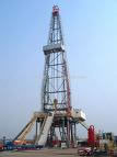
Trailer Mounted New Drilling Rig 1000hp for Sale
Trailer Mounted Drilling Rig for Sale
1000 hp Trailer Mounted Drilling Rig
New Built Mechanical Drilling Rigs for Sale
Description
I. Hoisting Equipment
i. Mobile drilling trailer mounted type 1000HP, with single drum drawworks, two
Detroit series 60 14.0 liter engines with two Allison S6610H transmissions with
hydraulic torque converter. Mast height 118 ft., load capacity-425,000 lbs. (210 ton API).
Rig mounted on a 4-axle chassis.
A. Group I. Basic Rig
a.
Drawworks – OEM-1000
i. Disc Brake System – Two (2) 60” O.D. x 4” Thick water cooled disc: Four (4)
brake calipers w/park feature, each caliper can develop 48,000 ft-lbs @ 100 psi.
Maximum 900 rpm calipers have a park feature rated @ 28,000 ft-lbs each. Manufacturer = Kobelt
ii. Air Clutch – Two (2) 30” diameter friction disc, slip torque rating 54,500 ft-lbs @ 100 psi,
maximum 760 rpm, 1664 sq in lining area. Manufacturer = Witchita.
iii. Drum 24” O.D. x 40” length with Lebus groove system
iv. Centralized Lubrication System
v. Drill line Diameter-1 1/8”
vi. Drive Chain - Four-strand, 1 ½” pitch
vii. Total Disc Brake Area - 1680 sq. inches
b.
Auxilary Brake
i. Air Operated: Water Cooled Disc with copper alloy wear plates, mounted to frame,
coupled directly to drum shaft. Two (2) 36” Disc rated @75,000 ft-lbs @100 psi
maximum 640 rpm.
ii. Size-236 or equal
iii. Maximum Pressure - 100 psi
iv. RPM-640
v. Direct Coupled Drum shaft.
c.
Combined Gear Box
i. Combined right angle drawworks drive drop box with one output shaft for rotary drive
and one output shaft (unused) for additional components.
1. One input shaft with 1810 drive flange.
2. Top right shaft - drawworks drive, air engaged 1.0 to 1 ratio keyed shaft
3. Top lower shaft - rotary drive, air engaged 1.1489 to 1 reduction ratio keyed shaft.
4. Bottom lower shaft – Future or additional components, opposite top lower shaft,
air engaged, 0.9787 to 1 ratio (1.0217 to 1 ratio increasing), 1810 drive flange.
ii. Gear type lubrication pump mounted intermediate shaft provides positive lubrication
to bearings.
d.
OEM 118’-0” x 425,000# Telescoping Mast
- The 118ft., mast provides is a telescoping
design, manufactured in accordance with API and Drilling Structures Int’l Inc.’s strict
quality control processes.
The mast includes an automatically deployed racking board.
i. A telescoping derrick with open face derrick design, manufactured to API 4-F
specifications. The open face design utilizes structural steel construction, which allows
for maximum block clearance. Derrick includes a ladder from rig floor to crown and a
block cradle with chain & hook for securing block during transport.
ii. Specifications
Mast Height : 118’
No. of Lines to Block - 8 or 10
API Operating Hook Load
- 8-Lines 340,000 lbs.
- 10-Lines 425,000 lbs.
Drilling Line Size : 1-1/8 in.
Racking Board Height - 55 ft., 58 ft., 70 ft.
Racking Board Capacity 5 in. Drill Pipe - 12,400 ft.
iii. Base Section
a. A-leg style base section hinged to carrier frame. (2) Turnbuckles attached from
bottom of derrick base to carrier frame allow for mast angle adjustment.The well-side derrick
legs have manual screw jacks.
iv. Lower Section
a. 6 in x 6 in x 3/4 in angle main legs, with 6 in x 4 in x 3/8 in rectangular tubing
“back” braces. Lower section of mast hinges to top of derrick base and rests on headache
rack during transport.
v. Upper Section
a. Angle construction. 6 in x 6 in x ¾” upper legs, with 3 in x 3 in x 3/8 in “back” braces. Upper
section rests inside lower section until mast is raised. Upper section then telescopes
hydraulically upward from lower section and locks in place with automatic latching pins.
vi. Crown Block
a. Crown block is set up for a 8 or 10 line string-up. Crown sheaves are grooved for 1-1/8 in.
Wire line. All sheaves are mounted on tapered roller bearings with grease certs for ease
of maintenance.
b. Crown includes: (1) one 30 in fast line sheave, and (4) four 24 in crossover sheaves.
vii. Racking Board
a. The mast includes an all welded racking board. The racking board automatically deploys
as the mast is extended.
viii. Derrick Raising System
a. The derrick is designed to utilize two, 72”x 9” x 3-stage, double acting raising rams and
one 50’ x 7” single-stage telescoping cylinder.
ix. Guylines
a. Derrick includes (2) load guys from the crown to carrier and (1) set of wind guys that meet or
exceed API specifications.
e.
Hydraulic Catworks
a. Hydraulic break out cylinder for breaking out pipe connections, 4 ft. stroke,
maximum pull load 20,000 lbs. Installed on the mast. Includes cable, roller guides and
hydraulic piping.
b.Hydraulic make up cylinder for making up pipe connections, 4 ft. stroke, maximum pull
load 20,000 lbs. Installed on the mast. Includes cable, roller guides and hydraulic piping.
c. Controls are located at the operator’s console
f.
Traveling Block Limit Switch (Crown Block Saver)
a. Safety device for limiting traveling block raising. Installed at the main drum to activate the
main brake when traveling block is up to a pre-determined height.
g.
Deadline Anchor
a. Dead line anchor to be used with compression type weight sensor. Drum type, mounted on
carrier frame in front of drawworks frame.
h.
Diesel Engine
a. Two Detroit series 60 - 14.0L engines rated at 600 BHP each@ 2100 RPM’s, 6 cylinders
(inline) complete with DDC electronic control system.
b. Includes: Radiator, Heavy Duty Blower, 24V starter and alternator, variable speed governor,
full instrumentation (ignition switch, ddr connector, electic throttle, electronic display module),
two (2) 12v batteries and spark arrestor muffler.
c. Specifications: 600 BHP @ 2100 RPM, 1650 lbs/ft @ 1100 RPM
i.
Transmission
a. 5 speed (6th gear locked out), automatic, Allison S6610H or equal w/torque converter,
oil cooler. Dual air/hydraulic operation. Max. capacity 850 HP, 2500 RPM, 2300 ft-lbs input.
a. Compound gear box, dual input, single output, may be drive with one or both engines.
b. Two input shafts, air engaged, 1810 drive flange (engagement of either input or a
combination of both)
c. Single output, 1810 drive flange, ration 1.0271 to 1 to combination gear box.
d. Gear type lubrication pump. Mounted to output shaft provides positive lubrication to bearing.
k.
Power Take-off
a. Chelsea 852 XB or equal, Used for hydraulic pump drive, mounted on transmission,
95 HP @ 1000 rpm output.
l.
Hydraulic System
a. Two hydraulic gear pumps, one 500 gallon hydraulic tanks with containment pan, filters,
heat exchanger and sight glass. Capable of producing 50 gpm @ 3000 psi, pressure return and
circulation filters with visual indicator, 3000 watts portable generator, inline flow meter,
system safety release valve, circuit breaker panel for heater/valve bank, operator panel
with selector switch.
b. Custom built valve bank, 15 station manifold, prewired control panel and hand held remote
with the following functions:
i. Mast lower/raise
ii. Mast telescope up/down
iii. Two (2) hydraulic pilot operated directional valve and joystick for winches.
iv. Six (6) leveling jacks.
v. D.S. sub raise/lower
vi. ODS sub raise/lower
vii. Make up/Brake out tong cylinders with remote torque adjustment
viii. Flow dividers for mast raise and sub cylinders
ix. Electrical control panel, remote controls and function switches for above
x. Velocity fuses on all cylinders for fall protection.
m.
Air System
a. Air system with on (1) 60 gallon receiver to provide air to main air line and brake system.
Includes air lines, control valves, pressure gauges.
n.
Air Compressor
a. Air compressors with direct drive, mounted on engine.
b. Reciprocal type, 28 CFM capacity
o.
Operator’s Controls
a. Operator’s console to include the following controls and instrumentation:
i. Main drum brake lever
ii. Main drum clutch controls
iii. Two engine throttles – One (1) hand and one (1) foot
iv. Shift levers for two 4-speed transmissions
v. Two emergency engine shut downs
vi. Hydraulic pump controls
vii. Two mud pump engine regulators
viii. Mud pump engine emergency shut down
ix. Mud pump clutch controls
x. Instrumentation Air Pressure Gauge
b. All air operated controls are located in the central part of the console and have identifying tags.
Console is located to provide good visibility of traveling block, work floor and racking board.
p.
Engine Emergency Shut Down
a. One engine emergency shut down valve for emergency engine stop. Located at the
operator’s console.
q.
Trailer Mounted
a. A heavy duty 4-axle trailer with air suspension and 109,000 lb. total capacity.
b. All lights and brakes are equipped for attachment to the truck
c. Spring brake chambers for safety.
r.
Tires (12.00 x 22.5, Pirelli Radial) 16 each
a. All tires, disc wheels, 16 tires mounted as dual. Tire rating 109,000 lbs. total, all tires inflated to 100 psi.
s.
Suspensions
a. One (1) two axle, single point bogey at rear.
b. Two single axles with air bags, air can be dumped for backing into position
c. All axles are 12.5 metric ton capacity.
t.
Four Pedestals for Hydraulic Jacks
a. Pedestals under front jack for rig stability. Four pedestals require. There are to be six jacks for
leveling the rig.
u.
Six Hydraulic Jacks
a. Six hydraulic leveling jacks to take off the load from the axle and provide horizontal position of the
rig during operation. Each jack is operated by its own controls and is equipped with screw with
thrust nut,which allows relieving hydraulic pressure from he jacks during rig operation. Controls are
located at the mast supports.
v.
Fuel Tank
a. Mounted on the side of the chassis
w.
Auxili
ary Hydraulic Winch (2 winches using one for spare)
a. Braden or equal hydraulic winch with 12,000 lbs. pull load at the first layer, 336 fpm @ 65 GPM
and 2400 psi.
b. Hydraulic brake and spooler
c. Sheave is mounted on the crown
x.
Rotary Table Drive
a. One rotary table drive with driveshaft and two air clutches(one for rotary on and off, second for emergency
shut down)
b. Controls are located at the operator’s console
y.
Rotary Table Drive Chain Gear Box
a. Includes three oil-greased shafts inside full-length guard, complete with sprockets, flanges, chains and
chain gear-box with one shaft to connect to rotary table. One lower section mounted on the trailer, one upper
section mounted on the sub and one flanged driveline between.
z.
Drill Line
a. 1 1/8” OD drill line, 6 x19s IWRC, 3000 feet
Group II - Substructure and Assessories
A. OEM Hydraulically Telescoping 17-425 Substructure
1) Material and labor to fabricate one (1) OEM hydraulic telescoping 17-425 substructure
as per the following:
i. Hydraulic Telescoping Substructure with:
- 425,000# Rotary beams
- 300,000# Setback.
- Clear height under rotary beams = 14’
- Transportation height 12’-6”
- Base dimensions 45’L x 12’-6”W
- Working floor dimensions 20’ x 26’
- Rathole and mouse hole locations
- Two tong backup posts
- Removable braces in cellar area.
- Provisions for attaching mast support beam.
- Supply and installation of four (4) hydraulic scoping cylinders.
- Pull out post for guy wires to front of mast.
- Removable flooring around rotary table area.
- B.O.P. Dolly and tracking.
The above substructure to be fabricated under A.P.I. 4F guidelines. Upon completion,
substructure to be tagged with OEM A.P.I. 4F
B. Mud Boat
i. Material and labor to fabricate one (1) mud boat. Mud boat complete with:
1. Supports under jacks on carrier.
2. Pipe guides for tires
3. Pin connections to mast support beam.
4. Loading hitches on one end
C. Mast Support Beam/Brake Water Tank/Trip Tank Combo
i. Material and labor to fabricate one (1) mast support beam/trip tank/brake water
tank combination. Combination complete with:
1.
Brake Water Tank
- Material and labor to fabricate one (1) break water tank. Tank to be
enclosed for rig up winterization.
a. Tank to have the following:
i. Tank bottoms to be 3/8” plate.
ii. Tanks constructed with ¼” v-crimp.
iii. Tank rims to be 4” square tubing.
iv. Access ladder
v. Man way
vi. Tong buckets, guides, and safety cage.
vii. Supply and installation of:
1. Two (2) 2 x 3 centrifugal pumps
2. Heat exchanger
2.
Trip Tank
– Material and labor to fabricate one (1) trip tank. Tank to be enclosed for
rig up winterization.
a. Tank to have the following:
i. Tank bottoms to be 3/8” plate.
ii. Tanks constructed with ¼” v-crimp.
iii. Tank rims to be 4” square tubing.
iv. Access ladder
v. Man way
vi. Tong buckets, guides, and safety cage.
vii. Provisions to mount:
1. One (1) 2 x 3 centrifugal pumps
3.
Mast Support Beam
– Material and labor to fabricate one (1) three runner mast support beam.
a. Support beam complete with:
i. Supports for carrier jacks and bottom base of mast.
ii. Loading hitches on both ends for tailboarding.
D. Rig Floor Stairways– All stairs to meet OSHA standards with no slip grip strut stair treads.
i. Three (3) 17’-0” stairway from substructure floor to ground level. Stairs to be built on
a 45-degree angle.
ii. One (1) 9’-6” stairway from top of the substructure to top of mud tank. Stairs to be built on
a 45 degree angle.
E. V-Door Ramp- Ramp to be fabricated to work with a 17-0” floor height substructure and
an 18” catwalk. Ramp to be fabricated with ½” plate and 3” pipe guides.
F. Catwalk– One 50’ x 5’-0” x 18” catwalk with snatch post mounted on one end.
G. Doghouse- House to be fabricated on a three-runner oilfield type skid with loading hitches on
both ends for tailboarding. House to have checker plated flooring, v-crimped wall
construction, and an arched type roof. House complete with the following:
1. 4’-0” porch on one ends
2. 2’-0” walkway on the back side of the doghouse running to full length.
3. Handrails around house perimeter.
4. One sliding doorway to rig side.
5. One swing type doorways on both ends with windows built in.
6. Two (2) windows on the back side wall
7. Knowledge box
8. Three compartment workbench.
Group III - Prime Mover Drive
A. Lighting System–Heavy Duty explosion proof Fluorescent and Mercury Vapor
Lightning System designed to use with Mast and Substructure, Mud System, complete
with Plug, Receptacles, Cable, Cable Clamps and all necessary Leads and fitting. Lighting
System consist of: Mast and Racking Platform, Substructure Lighting, Mud Tanks and
Mud Pumps, and Utility House, including Battery emergency light at Driller’s console
certified for Class 1 Division 2.
B. Engine/Generator/Part/Change Package
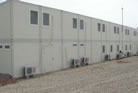
a. Utility House - “New” - Material and labor to fabricate one (1) utility house. House (43’x 12’ x 9’)
to be constructed on an oilfield type skid (45’x 12’x 18”) with loading hitches on both
ends for tailboarding. Top of skid covered with ¼” checker plate.
i. Parts/change house to be complete with:
1. Twenty (20) lockers.
2. Changing bench near lockers.
3. Two sets of shelves on each wall running 8’-0”.
4. One (1) bench on each wall. Bench compartments to be 5’-0” with folding bench.
Two compartments to have ventilation to the outside for paint storage.
ii. Generator house complete with:
1 One (1) 8’-0” sliding door on side of the generator location
2. Provisions for mounting one (1) electrical plug panel.
3. Radiator end of skid left open.
4. Skid designed for generator tie downs to be mounted on cross beams of skid for safety.
b. Generator – Two (2) Detroit 60 Series 14L.
c. Electrical Specifications
i. Item 1 – Clarification
1. Prime mover specifications were not provided; IEC Systems assumes the engine
and generator sizes as listed in this proposal.
2. The generator house will be designed to accommodate the “Three Tank Drilling
Rig Standard” and thus be interchangeable with all rigs that meet the standard
3. IEC System proposal is based on performing the installation in Houston, Texas.
All components listed below will be installed and tested
4. Customer will furnish the voltage regulator and voltage rheostat
ii. Item 2 – Generator Houston Electrical System For a Mechanical Rig
1.
Generator House 480 VAC Switchboard
a. 1 ea - A/C Generator Control Panel by IEC Systems for the control of two (2),
450 kW, 480 volt, 3 phase, 4-wire, 60 Hertz, A/C generators.
b. Switchgear to contain full instrumentation and will not be designed for full
parallel operation of generators.
c. Switchboard will be NEMA Type 1 enclosure with ASA #61 gray enamel finish,
designed to meet NEMA and OSHA specifications.
d. All nameplates will be constructed of plastic plates, black on white for names
and red on white for warnings.
Generator controls mounted in the switchgear will consist of:
2 - Generator Main Circuit Breakers (Gen PWR)
2 - Generator "Power Available" Indicating Lights
2 - Voltmeters
2 - Voltmeter Switches
2 - Ammeters
2 - Ammeter Switches
2 - Frequency Meters
2 - Reverse Power Relays
1 - Ground Detection System
2 - Governor Control Switches
2 - Wire to Customer Furnished Voltage Regulators
2 - Wire to Customer Furnished Voltage Rheostats
1 - Lot Current Transformers, Potential Transformers, Fuse Blocks, Fuses,
Buss Bar, Switchboard Wiring, and related equipment
Switchboard will be fully assembled, wired, and shop tested.
2.
Generator House 480V Motor Control Center (MCC)
a. 1 ea - 480 Volt, 3-phase, 60 Hertz A/C Motor Control Center, equipped with braced horizontal
and vertical bus
b. Enclosure will be NEMA Type 1 with front only access
c. Motor starters will be combination, full voltage- non-reversing with 3-pole overload
blocks, heaters, control power transformer, operating handle, fuses and start/stop
controls in cover with red "RUN" indicating lights
d. 480V MCC Motor Starters
i. Five (5) Size 4 Starters for:
1 ea 60 HP Mud Mixer 1
1 ea 60 HP Mud Mixer 2
1 ea 60 HP Desander
1 ea 60 HP Desilter
1 ea Spare
ii. One (1) Size 3 Starter for:
1 ea 40 HP Trip Tank
iii.Five (5) Size 2 Starters for:
1 ea 20 HP Drill Water 1
1 ea 20 HP Drill Water 2
1 ea 25 HP Brake Cooling Pump 1
1 ea 25 HP Brake Cooling Pump 2
1 ea Spare
iv. 480 V MCC Motor Feeder Circuit Breaker
1. 1 ea - 150 AMP 3 Pole Circuit Breaker for Camp Feeder
3.
Generator House 480V Distribution Panel Boards
a. 1 ea - 480V POWER DISTRIBUTION PANEL BOARD (P1)
i. 480V, 3-Phase, 3-Wire
ii. NEMA 1 Enclosure
iii. 600A MLO with Feed-Thru Lugs
iv. 36 CKT with branch Circuit Breakers for the following loads:
a. 1 ea - 100A/3-Phase CB for 75 KVA Lighting Transformer
b. 1 ea - 60A/3-Phase CB for BOP Accumulator (30 HP)
c. 1 ea - 60A/3-Phase CB for Spare
d. 1 ea - 30A/3-Phase CB for Agitators 1, 2 Feeder (10 HP each)
e. 1 ea - 30A/3-Phase CB for BOP House Heater (15 kW)
f. 1 ea - 30A/3-Phase CB for Change House Heater (15 kW)
g. 1 ea - 15A/3-Phase CB for Liner Washer 1 (3 HP)
h. 1 ea - 15A/3-Phase CB for Liner Washer 2 (3 HP)
i. 1 ea - 20A/3-Phase CB for Fuel Pumps 1 & 2 Feeder (3 HP each)
j. 1 ea - 20A/3-Phase CB for Shale Shaker 1 & 2 Feeder (5 HP each)
k. 1 ea - 30A/3-Phase CB for Spare
L. 1 ea - 30A/3-Phase CB for Wireline (15 HP)
b. 1 ea - 480V DISTRIBUTION PANEL BOARD (P2)
i. 480V, 3-Phase, 3-Wire
ii. NEMA 1 Enclosure
iii. 600A MLO with Feed-Thru Lugs
iv. 30 CKT with branch Circuit Breakers for the following loads:
1. 1 ea 100A/3-Phase CB for Hydraulic Power Unit (HPU), (50 HP)
2. 1 ea 100A/3-Phase CB for Air Compressors #1 & 2 (25 HP each)
3. 1 ea 20A/3-Phase CB for Vacuum Degasser (7.5 HP)
4. 1 ea 30A/3-Phase CB for Dog House Heater (15 kW)
5. 1 ea 60A/3-Phase CB for Agitators 3, 4, 5 Feeder (10 HP each)
6. 1 ea 30A/3-Phase CB for Hopper House Heater (15 kW)
7. 1 ea 40A/3-Phase CB for Spare
8. 1 ea 60A/3-Phase CB for Spare
9. 1 ea 30A/3-Phase CB for Spare
10. 1 ea 30A/3-Phase CB for Spare
4.
Generator House 120/208 Distribution Panel Board
a. 1 ea - 120/208V DISTRIBUTION PANEL BOARD (P3)
i. 120/208V, 3-Phase, 4-Wire
ii. NEMA 1 Enclosure
iii. 225 MLO, Top Feed
iv. 42 CKT with branch (124/240V-10 KAIC) Circuit Breakers for the following loads:
1. 1 ea - 100A/3-Phase CB for Rig Floor Lighting Panel
2. 1 ea - 100A/3-Phase CB for Spare
3. 1 ea - 100A/3-Phase CB for Boiler House Feeder
4. 1 ea - 60A/3-Phase CB for Spare
5. 1 ea - 30A/3-Phase CB for Spare
6. 10 ea - 20A/1-Phase CBs for Lighting Circuits 1 thru 10
7. 1 ea - 20A/1-Phase CBs for Engine/Generator House Steam Heater Blowers
8. 1 ea - 20A/1-Phase CBs for Trip & Shaker Tank Steam Heater Blowers
9. 1 ea - 20A/1-Phase CBs for Mud Pump 1 & 2 Steam Heater Blowers
10. 1 ea - 20A/1-Phase CBs for Mixer Skid Steam Heater Blowers
11. 1 ea - 20A/1-Phase CBs for Engine/Generator House Lighting Circuit
12. 1 ea - 20A/1-Phase CBs for Generator 1 & 2 Block Heater Feeders
5.
Generator House Plug Board
a. 1 ea Metal shroud protected weatherproof receptacle panel with matching plugs for all the
above starters and circuits having cables that exit the Generator House.
b. Receptacles to have protective vapor proof caps. Plugs and receptacles will be
permanently identified.
c. 480V Plug and Receptacle sets provided for the plug board include all loads listed above in
Section C and D (MCC and Panel Board Loads)
d. Additional Plug Board Spare Plugs and Receptacles
6 ea 30A, 3-Pole, 480V
5 ea 60A, 3-Pole, 480V
2 ea 100A, 3-Pole, 480V
6.
Generator House 480/208-120V Rig Lighting Transformer
a. 1 ea 75 KVA Transformer with 480V Primary and 120/208V Secondary mounted in a
drip-proof enclosure.
Primary Power will be from the P1 Panel Board.
7.
Generator House Power and Control Cabling
a. 1 lot A/C Power and Control Wiring by IEC Systems to connect two 450 KW, 480 volt,
60 Hertz A/C generators to 480V Switchboard
b. All A/C generator power cables with 90 0C rates insulation sized/de-rated for use in
45 0C ambient atmosphere.
c. 1 lot Glastic Plates to prevent excessive heat caused by electrical fields where power
cables enter generators.
d. 1 lot A/C Power and Control Wiring to connect A/C generator control panel to:
i. MCC
1. P1 Panel Board
2. P2 Panel Board
3. P3 Panel Board
4. 75 KVA Lighting Transformer
5. Generator House Plug Board (receptacles)
8.
Generator House Lighting
a. Generator Sheds Lighting receptacle string complete with plugs and receptacles,
cable, cable clamps, and all necessary leads and fittings to accommodate the following:
i. 4 ea - C1D2 Hazardous Area fluorescent fixtures complete with lead
ii. 1 ea - C1D2 Hazardous Area Metal Halide floodlight fixture complete with lead
iii. 1 ea - Mounting Stanchions for Floodlights
Group IV - Rotating Equipment
B. “New” American Block Traveling Block and Hook
a. 250 Ton Traveling Block, API load rating: 250 Ton, sheave groove 1 1/8”.
C. “Rebuilt” National C275 Rotary Table and Accessories
a. 27 ½” rotary table with 27 ½” table opening, static load capacity: 650 ton, gear ratio
3.6:1, torque cap: 30,000 ft-lbs @ 60 rpm.
D. “Rebuilt’ Rotary Swivel
a. 250 Ton
Group V - Circulating Systems
A. Two “New” Mechanical Drive 1000HP Mud Pumps
a. Two (2) “New” Eweco - 1100HP Mud Pumps
b. Two (2) “New” Detroit D2000 Engines
c. Unitized on one common skid with:
i. Model C-300-100F(H) OWI Torque Converter
ii. Belt Drive
iii. Dual 24” Eaton Airflex
iv. Drum Hub for 24” Dual Clutch
v. Drum Flange, external 24”
vi. 5 x 6 Centrifugal pump
d. Control system including:
i. Air throttle
ii. Air valve to engage and disengage clutch
iii. Hoses and mounting hardware.
B. Two Tank 850 BBL Mud System- Material and labor to fabricate one (1) two
tank 850 bbl mud system as per our discussions. OEM to completely fabricate tanks
(40’ x 10’-6” x 7’-0”) on a three runner oil field type skid (50’ x 7’-10” x 8”) with loading
hitches on both ends for tail boarding. Tanks to have internal ladders to each compartment,
equipment supports, fold down type handrails and covered with galvanizes bar grating
Mud system to consists of the following:
i.
Shaker Tank
– Four equal compartments
-Shale Pit
• 10’-0’’ compartment
• One (1) cleanout
• One (1) overflow
- Desander Pit
• 10’-0 compartment
• One (1) cleanout
• One (1) overflow
• One (1) 6” suction line from 5 x 6 centrifugal pump.
• One (1) 8” equalizer. Bottom mounted with top mounted handle.
- Desilter Pit
• 10’-0’’ compartment
• One (1) cleanout
• One (1) overflow
• One (1) 6” suction line from 5 x 6 centrifugal pump.
• One (1) 18” equalizer. Bottom mounted with top mounted handle.
• Equipment supports for one (1) 10 HP agitator
- Degasser Pit
• 10’-0’’ compartment
• One (1) cleanout
• One (1) overflow
• One (1) 8” bottom equalizer and one (1) 8” top equalizer.
• Equipment supports for one (1) 10 HP agitator.
- 9’-0’’ Porch
• Able to accept two (2) 5 x 6 centrifugal pumps
• 10’’ equalizer line to Suction Tank.
• Covered with ¼’’ Chk’d floor plate.
• Overhead plated roof.
ii.
Suction Tank
– Two Compartments.
- Suction compartment
• 30’ – 0’’ compartment
• One (1) cleanout gate.
• Two (2) 6” suction lines going to main mud pumps.
• Equipment supports for two (2) 15 HP agitators.
- Pill Compartment
• 10’-0’’ compartment.
• One (1) cleanout gate.
• One (1) 8” equalizer. Bottom mounted with top mounted handle.
• One (1) overflow
• Equipment supports for one (1) 10 HP agitator
- Porch
• Able to accept two (2) 5x6 centrifugal pumps.
• 6’’ line to both pumps
• One (1) discharge dumping line
Pill Tank
Suction Tank.
iii.
Accessories
1. Single slide for shaker. Slide to mount to the side of the tank and fold down
during transportation. Slide complete with 6” pipe end for hose hook up in the field.
2. Single slide for desander. Slide to mount to the side of the tank and fold down
during transportation. Slide complete with 6” pipe end for hose hook up in the field.
3. Single slide for desilter. Slide to mount to the side of the tank and fold down
during transportation. Slide complete with 6” pipe end for hose hook up in the field.
4. Fold down type walkways around shaker area complete with galvanized grating and
handrails. Walkways to fold down during transport.
iv.
Solid Control Equipment
1. Four (4) Mission Magnum 6 x 5 x 11 magnum1 with a 10.5 inch impeller, mechanical
seal and hard iron material, all mounted on a mission fabricated steel base with woods
style coupling, OSHA type coupling guard and a 75 HP 1750 RPM, 3 PH, 230/460 Volt,
60 Hz explosion proof electric motor.
2. Three (3) Derrick DE-AG-10 Agitators complete with 10 HP, 1800 RPM explosion
proof C-face motor bolted to a gear box. Including shaft stabilizer, shaft and impeller.
3. Two (2) Derrick DE-AG-15 Agitators complete with 15 HP, 1800 RPM explosion
proof C-face motor bolted to a gear box. Including shaft stabilizer, shaft and impeller.
4. One (1) Derrick two cone desander.
5. One (1) Derrick sixteen cone desilter.
6. One (1) Hopper with venturi.
7. One (1) Derrick Vacuum degasser 1200 GPM. Skid mounted with heavy duty 3 HP
explosion proof 230/460 volt, 60 Hz, 3 Ph, 1800 RPM motor and manual starter with
heavy duty vacuum pump.
8. Two (2) Derrick Flo-Line Cleaner 503 Shale Shakers w/weir feed complete with
three panel screen frame, support structure, and explosion proof electrics with
the following options:
1. A.W.D. (+7 deg uphill to –1 deg downhill)
2 Standard Screen Underflow hopper
3. Weir feed
4. Super G Vibrations Motors
5. Single side tensioning system
9. 36” Poor Boy Degasser on a separate skid.
VI.
BOP
A. Six (6) Station Accumilator
B. Choke & Kill Manifold
C. Note – BOP to be supplied by others (Not include in pricing.)
VII -
Utilities
A. Air Compressor & Receiver
a. Two (2) Gardner Denver, ST-30, Electra-Saver II, rotary screw air compressor,
Model EBE99Q. 30 HP, 460 volts, 3 phase, 60 HZ, TEFC, with NEMA 4 Control Enclosure.
b. Two (2) Steel Fab, 400 gallon, vertical air receivers with full skirt, 200 psi working pressure.
Part # A12614. Unit is California Coded.
c. One (1) RNC250 air dryer for 250 CFM.
VIII.
Instrumentation
A. Drift Indicator
Totco Double Recording Drift 0 to 8 and 0 to 14. Clock complete with following:
- 1 ea. Godevil Kit
- 1 ea. Chart tool & Chart Reader
- 1 ea. Tool Maintenance Box w/ Tool
- 100 ea. Chart 0 to 8° and 0 to 14°
- 10 ea. Rubber Finger Stabilizer
- Fishing Tool 7 rope sockets
B. Indicator/Gauge & Counter
EMS-2 or Equivalent Rotary Torque indicator, Weight indicator, and Tong torque gauge,
Circulating pressure gauge, two (2) ea. Pump stroke counter.
C. Drilling Recorder
EMS-2 or Equivalent Drilling recorder, 9 pen (weight, torque, penetration rate, pump
pressure, rotary rpm). (Diameter 103 Dan Kurang 6 Buah Printed Circuit Board).
D. PVT
EMS-2 or Equivalent Pit volume totalizer, single channel with audio alarm and
warning lights, four pit transmitters totalizing relay, gain and loss gauge with gauge
zero devices. Full digital instrumentations.
E. Flow-Shoe-Device
EMS-2 or Equivalent Device complete with recorder and alarm system
Group IX - Fabrications
A. Accumulator/Junk Bend/Air Package Combo
a. Material and labor to fabricate one (1) accumulator/pipe bend skid as per our conversations.
OEM to fabricate a three runner oilfield type skid (40’ x 10’ x 12”)
covered with ¼” check plate. Piping to be done during rig up. Skids complete with:
i. One (1) arched type roof and enclosure.
v. Mounting supports for two (2) vertical air receivers.
vi. Mounting supports for one (1) accumulator.
vii. Mounting supports for:
1. Two (2) air compressors
viii. Access doors
1. One 36” swing type door way
2. Two (2) 48” double door way.
B. Parts/Mechanic Shop - “New”
Material and labor to fabricate one (1) parts/change house. House (38’x 10’x 9’) to be
constructed on an oilfield type skid (40’x 10’x 12”) with loading hitches on both ends for
tailboarding. Top of skid covered with ¼” checker plate. House to be complete with:
- One (1) work bench and One (1) Table
- Two sets of shelves on each wall.
- Four (4) storage benches.
C. 500 bbl Water Tank
Material and labor to fabricate one (1) 500 bbl water tank as per our conversation. Tanks
fabricated on oilfield type skids with loading hitches on both ends for tailboarding. Skid ends
to be covered with ¼” check plate.
Tanks complete with the following:
- Two (2) 3 x 2 x 11 Centrifugal pumps with 25 HP Motors
- Suction and Discharge Piping.
- Two (2) ladder rung to top of tank (In and Out)
- 4” Fill cap
- 2” Outlet
- 1” Drain
D. One (1) 12,000 Gallon Fuel Tank
Material and labor to fabricate one (1) 12,000 gallon fuel tank as per our conversation.
Tanks fabricated on oilfield type skids with loading hitches on both ends for tailboarding.
Skid ends to be covered with ¼” check plate. Tanks complete with the following:
- Two (2) fuel transfer pumps
- One (1) filter system.
- Suction and Discharge Piping.
- Two (2) ladder rung to top of tank (In and Out)
Top and Side man ways, 4” Fill cap, 2” Outlet, and 1 ½” Drain
E. Cable Trays- Material and labor to fabricate one (1) lot of cable trays as per the following.
Cable trays to be fabricated as follows:
- Two (1) 40’-0” sections from substructure to fuel tank.
- One (1) 35’-0” section from mud tanks to main trays.
- One (1) 20’-0” section from substructure to main stairs.
- Cable trays complete with the following:
• Hinged doors in 5’-0” sections with chain for each doorway.
• Flat expanded metal running the length of each tray.
• ½” round bar at each end of cable tray to provide protection when pulling wires.
F. Mud Gas Seperator and Transportation Skid - “New”
- Material and labor to fabricate one (1) 36” poor boy degasser and skid. Gas buster to me
mounted on a three-runner oilfield type skid with loading hitches on both ends for tailboarding.
Gas buster complete with:
• 36” Pipe with weld caps on both ends.
• Internal baffles.
• All piping and pipe brackets.
• Gas buster to elevate to working condition to allow operation under half full conditions.
• Gas buster to be mounted in lay down position for transport and to be raised by
truck for operation.
Group X - Rig Up Items
A. High Pressure Piping
a. Material and labor to fabrication one (1) lot of high-pressure piping. All piping to be 4”
schedule 160 and all unions to be weld type 1002. High pressure piping complete
as per the following:
i. Standpipe
1. Standpipe to be located on the Off-Driller’s Side.
2. Standpipe to have hammer union breaks at mast sections so it can me transported
without being taken off the mast.
ii. Standpipe Manifold
1. The standpipe manifold will be complete with manifold type tee with two 2” outlets.
Outlets to have hammer union connections only.
2. The 4” outlets to have a 4” gate valve on the top of the cross.
iii. High Pressure Line
1. The high-pressure line will run from the bottom of the standpipe manifold to the
side of the mud boat
2. The cellar line will be mounted to the mast support beam.
3. There will be hammer unions at break of the substructures for transportation.
B. Structural set and assemble:
a. Mast and Substructure
i. Mast accessories.
ii. Install flooring, handrails, v-door, stairs, etc.
C. Set and align
a. Rotary Table
b. Drawworks
c. Doghouse
d. Utility house control panel and foot drawworks console.
e. Mud Pumps
f. Mud system
g. Brake water/trip tank
h. Water Tank/Fuel Tank
i. Catwalks and pipe racks
j. Cable Trays
k. Koomey/Junk basket
D. Piping, Fittings, hoses, valves, etc.
a. Water Supply
i. To Mud system and mixing system
ii. Rig Floor
iii. Brake water system
iv. Feed and return lines from brake water tank to drawworks drum and brake.
v. Fuel System
1. To feed and return lines from duel tank to generator set.
vi. Air System
1. Air Supply for accumulator unit and rig floor
2. Hose connections from rig floor air manifold to drawworks control console, air
hoist and other floor tools
a. To generator set engine starters
vii. Miscellaneous
1. Vibrator hoses.
viii. Electrical Rig Up
ix. Testing
1. Fill mud tanks with water
2. Provide lube products to all machinery.
3. Provide Fuel for testing
4. Circulate water through mud system
5. Run air compressors.
6. Pressure test all high pressure lines and connections to working pressure
7. Run all solids control equipment.
8. Load test generators
9. Test all SCR assignments.
x. Rig Down
1. Rig down and assist in load out on customer furnished trucks.
Price & terms : Please enquire using the email form below.
If you cannot find the vessel, crane, rig or equipment that you need,
please send us an email to mail@worldoils.com stating your
requirements and we shall find it for you.
We can arrange delivery of equipment and towage of rigs and vessels where needed.
The details mentioned above are believed to be accurate but are not guaranteed.
---------------------------------------------------------------------------------------------------------------
Search words (for official use only) :
Mechanical Trailer Mounted Rig for Sale
1000hp New Land Drilling Rig in USA
Trailer Mounted Rig for Sale
Mechanical Drilling Rig
1000 hp for Sale
Trailer Mounted
Land Drilling Rig for Sale
-----------------------------------------------------------------------------------------------------------
.png)
.png)
.png)
.png)
.jpg)

.png)
.png)
.png)
.png)
.png)
.png)
.png)